Conveyor Drive System
Fluid Coupling Conveyor Drive System
Conveyor Drive System is prevalent across multiple material handling applications and high torque conveyor processes, making them one of the modern facilities’ most significant and well-balanced plant assets.
A Fluid Coupling Conveyor Drive system allows a controlled amount of slip between the input and output, or the drive and the buffer, without having mechanical interaction. Fluid coupling works by transferring rotational force from one shaft to another using transmission fluid.
Due to this, fluid couplings provide significant benefits in power transfer scenarios. With just about no wear, the fluid couplings transfer mechanical power from an electric motor to a gearbox.
For highly reliable and effective drive systems in the mining and raw materials processing industries, Voith produces fluid coupling solutions. Voith engineers its drive solutions—from individual couplings to complete drivelines—to fit any drive system.
Hydrodynamicity underlies the Voith fluid coupling, based on Foettinger’s Principle. Two bladed wheels, a pump wheel, and a turbine wheel, along with an outer shell, make up the majority of its components. They have set the two wheels against each other. There is minimal mechanical wear throughout power transmission, and there is no mechanical contact between the components that transmit power.
The coupling runs on a set quantity of operating fluid, which is typically mineral oil. Water-friendly design is available on demand. The drive motor transfers its torque to the pump wheel, converting it into kinetic energy of the operating fluid. The turbine wheel then converts this kinetic energy back into mechanical energy.
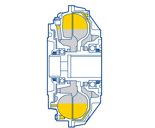
The system offers three set operation modes, which are:

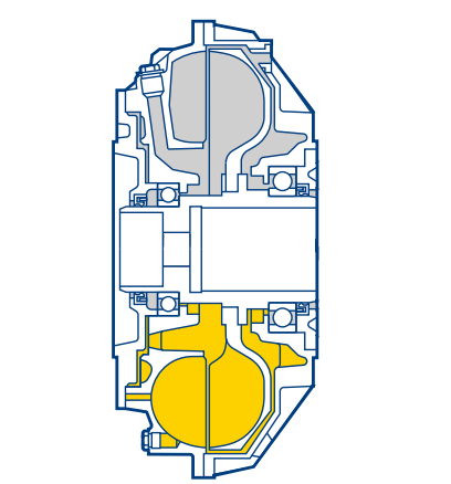
Standstill
In this operational state, the entirety of the coupling’s working fluid remains stationary.
Start-Up
The flow state in the connection becomes stationary due to the low-speed differential between the pump and the turbine wheel also referred to as nominal slip. The driven machine transmits only the torque that it requires.
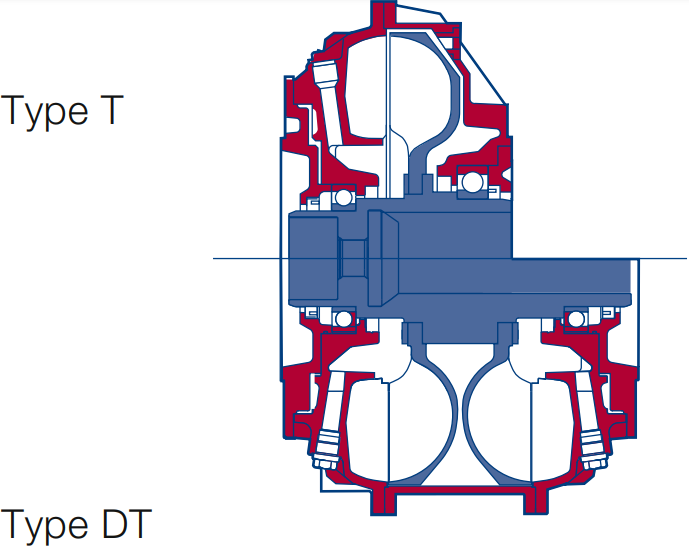
Fluid Coupling Conveyor Drive type T and DT — The Basic type
The flow state in the connection becomes stationary due to the low-speed differential between the pump and the turbine wheel also referred to as nominal slip. The driven machine transmits only the torque that it requires.
- Bucket-wheel excavators
- Bucket-wheel elevators
- Mixing, kneading, and stirring machines.
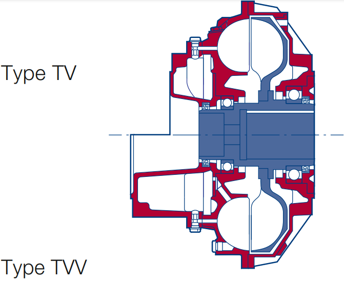
Fluid Coupling Conveyor Drive type TV and TVV — Smoother Start-Up
In the TV type, the coupling’s outer wheel is flange-connected to a “delay-fill chamber”. Whenever the coupling is at a halt, a part of the working fluid is stored in this chamber, which reduces the volume in the working circuit.
Hence, at motor start-up, the coupling transmits lower torque, making an unloaded motor start. The working fluid smoothly accelerates the driven machine as it moves from the delay-fill chamber into the working circuit once the motor reaches its operational speed.
Moreover, the delay-fill chamber can be enlarged if necessary on TVV type, amplifying its effects and reducing the coupling torque during motor start. This also leads to a longer and smoother start-up process for the driven machine. In some cases, the delay chamber’s functionality can be enhanced further by using centrifugally controlled valves (type TVF) or hydrodynamic filling (type TVY).
- Tube mills
- High-inertia machines
- Belt conveyors
- Crushers
- Centrifuges, decanters
Fluid Coupling Conveyor Drive type TVVS — The Innovative One
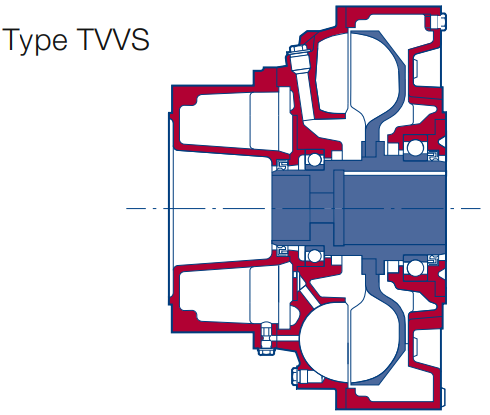
The TVVS type incorporates an annular chamber shell along with an enlarged delay chamber. This additional chamber within the coupling shell helps to decrease the starting torque. Centrifugal forces normally lead the operating fluid from the working circuit to fill the outer chamber as the startup process begins.
When a TVVS coupling’s working circuit is significantly less filled, the transmitted torque during motor run-up is reduced. This effect is less pronounced in couplings without annular chambers. The fluid gradually drains from the delay chamber into the working circuit, which is followed by an increase in torque.
It automatically adapts to changing belt loads by gradually building up torque.
- Belt conveyors
- High-inertia machines
Fluid Coupling Conveyor Drive type TRI and TVRI — For Pulley Drives
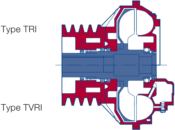
The bearing cover supports a V-belt or flat belt pulley that allows for various transmission ratios and can be easily replaced when needed. Engineers typically mount TRI and TVRI fluid couplings overhung on the motor shaft, using the coupling hub’s bearing cover to handle the belt force. TRI couplings serve as both start-up devices and overload protectors, while TVRI types—with an added delay chamber—deliver extremely smooth start-ups.
- Centrifuges, decanters
- Mixers
- Crushers
- Fans